
Static Object Collision
Collision Concepts
About Collisions
Collision geometry, often called a “collider”, defines how an object interacts with the player and the environment. It represents the shapes that physically block character movement, obstruct bullets, and determine where bullet impact decals appear.
In practice, collision geometry is contained within the object’s .dag file and
outlines specific parts of the object. Further details on this structure will be
provided later.
Note
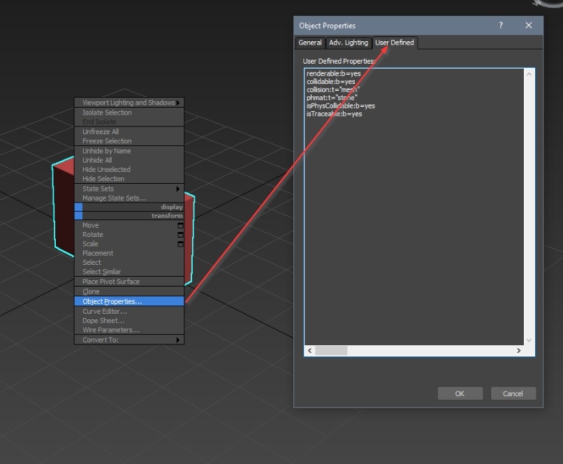
To avoid the need to search through the document, here is a summary of common and project-specific collision parameters:
Common parameters (used in all projects):
renderable:b=yes: Enables rendering of the node’s visual geometry.collidable:b=yes: Enables the node to participate in collision calculations.collision:t="mesh": Defines the collision type. Supported values aremesh,box,convex, andcapsule.phmat:t="stone": Specifies the physical material used for collision.
Parameters specific to daNetGame-based projects:
isPhysCollidable:b=yes: Enables the collision for physical interactions such as walking, vehicle movement, and object placement.isTraceable:b=yes: Enables the collision for traces, including shooting, object interaction, and bullet decals.
Collision Placement
In War Thunder, collision geometry is typically placed in the final LOD (Level of Detail) of the object, excluding LOD03. Most commonly, it resides in LOD01 or LOD02. If the object has only one LOD (LOD00), the collision is placed there.
In daNetGame-based projects, collisions are generally placed in LOD01.
During the resource
building process,
collision geometry is automatically collected into a collision pack based on the
rules defined in the .folder.blk file.
If the collision shown in the Asset Viewer does not match what was authored, consider the following possible causes:
The collision geometry was placed in the wrong LOD.
The collision was not exported with the LOD.
Collision properties were missing or incorrectly configured.
The
.folder.blkfile is referencing the incorrect LOD for collision.
Collision Parameters
To ensure the engine correctly processes collision geometry, it must be placed in the appropriate LOD and have the required parameters assigned. These parameters are applied to the collision object in 3ds Max, where such objects are referred to as nodes in FAR.
There are two ways to assign these parameters:
Within FAR: Parameters can be defined directly using a script block. For clarity, they are illustrated below using code examples with comments.
In 3ds Max: Parameters can also be assigned via the object’s properties.
Let’s review the full list of parameters using daNetGame-based project as an example:
script{
// Common parameters
  renderable:b=yes    // Display the visual geometry of the node
  collidable:b=yes    // Use the node for collision calculations
  collision:t="mesh"  // Collision type: "mesh" (can also be box, convex, capsule)
  phmat:t="stone"     // Collision material

// daNetGame-based project parameters
  isPhysCollidable:b=yes // Use collision for physical interactions (walking, vehicle movement, object placement, etc.)
  isTraceable:b=yes      // Use collision for traces (shooting, object interaction, bullet decals, etc.)
}
Important
If LOD geometry is being used for collision processing, ensure that the required parameters are correctly assigned to that geometry. It is not necessary to duplicate the geometry or create a separate object specifically for collision purposes.
General Parameters
These parameters are used across all projects:
Parameter: renderable:b=yes/no
This parameter controls whether the collision geometry is rendered.
yes: The geometry is rendered (default).no: The geometry is not rendered.
Note
This parameter is currently non-functional, but it must be specified since it could be activated in the future.
To ensure the collision geometry is not rendered:
Assign it the material
gi_black(this material is not rendered by the engine).Set
renderable:b=noin the properties.Uncheck the renderable box in the same properties.
Parameter: collidable:b=yes/no
This parameter determines whether the collision is functional.
yes: The collision is active (default).no: The collision is inactive.
Both visual geometry and collision geometry require this parameter. Visual geometry typically should not have collisions, while collision geometry must have it enabled.
Note
We assign this parameter to both collision geometry and visible non-collidable geometry.
For collision geometry:
collidable:b=yesFor visible non-collidable geometry:
collidable:b=no
Parameter: collision:t=""
This parameter defines how the collision geometry is interpreted. Currently, there are four supported collision types.
Type: mesh
The default and most resource-intensive collision type. It represents the geometry with full accuracy, exactly as it is.
Example: The mesh type is the default collision type, so specifying this
parameter is optional. This behavior originates from War Thunder, where the
.folder.blk file could sometimes force collisions to be treated as boxes. To
ensure that certain objects retained mesh collisions, the parameter had to be
explicitly set. In daNetGame-based projects, mesh collisions are used by
default without needing to specify the parameter.
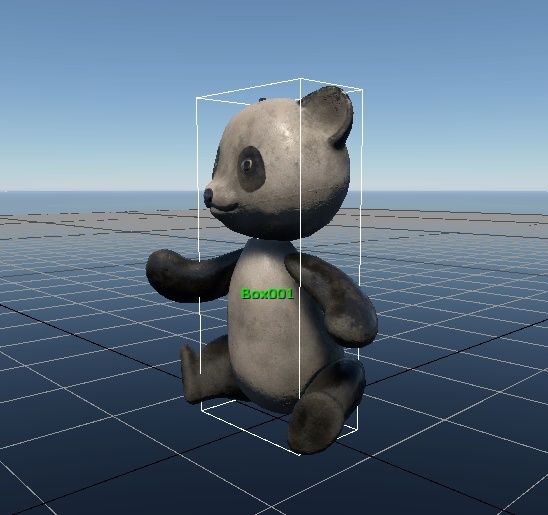
Type: box
A simple rectangular box is the most lightweight and efficient collision type. When this type is assigned to a collision object, it creates a box based on the object’s bounding box and uses it as the collision shape.
This collision is treated as a basic box, not as a detailed mesh. In practical terms, it behaves more like a primitive object in 3ds Max rather than a fully editable poly mesh.
Warning
If you created a box-shaped collision but did not set the collision:t="box"
parameter, you’ve actually created a mesh collision in the shape of a box.
The collision:t="box" attribute is required for the collision to be treated as
a true box.
A simple way to check:
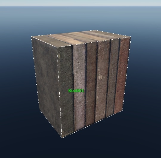
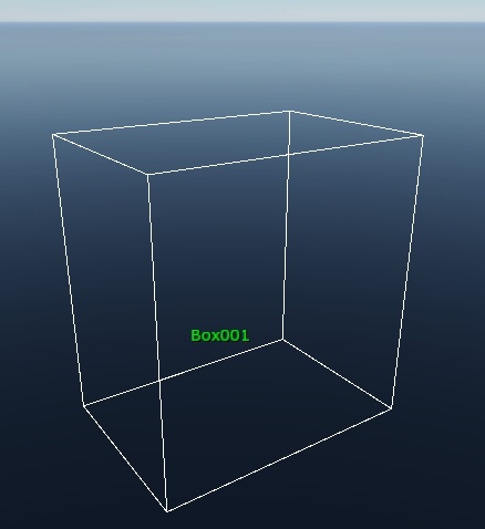
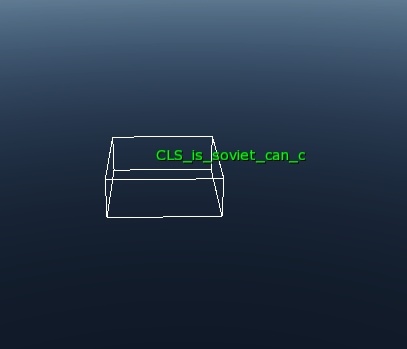
A proper
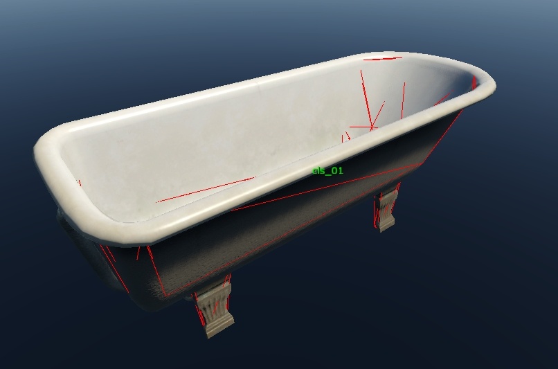
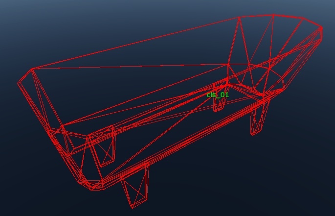
boxcollision in Asset Viewer appears as a box with white polygon edges (not triangle edges, those aren’t shown).A
mesh“box” in Asset Viewer appears as regular geometry with red/green triangle edges.
Example 1: The box collision type is ideal for rectangular or small
objects (up to mid-shin height), where the overall shape can be accurately
represented by a simple box. It is the most performance-efficient option.
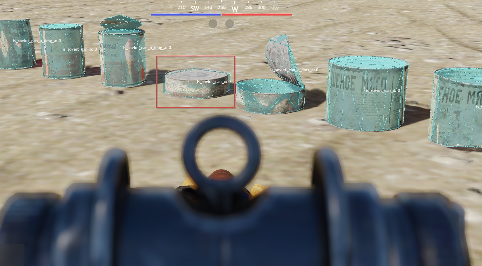
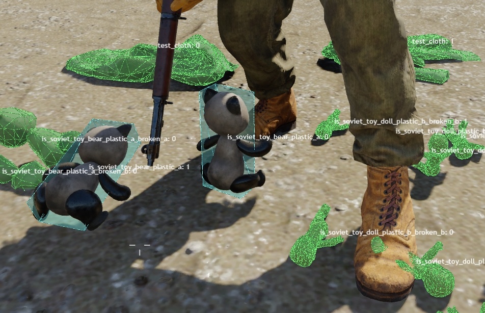
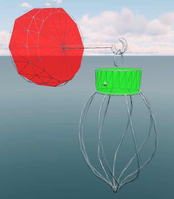
Example 2: Small easily breakable objects that do not require detailed
collision such as a tin can can use the box type for better performance.
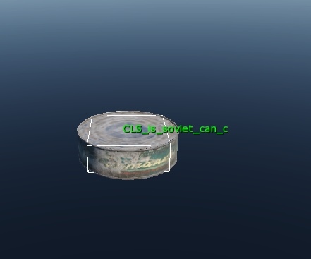
Here is how it looks in-game with a box collision:
Example 3: Small decorative items can also use box collisions. These
objects are not part of gameplay and will not be specifically targeted
(excluding rare edge cases).
Type: convex
Convex geometry. Processed more efficiently than a mesh but less efficiently
than a box.
Unlike a
box, this type does not generate a bounding box around the geometry; it uses the actual convex shape.If the geometry is not
convex, errors will appear in Asset Viewer (this will be explained later).
As with box, convex collisions are only recognized as such when this
parameter is specified. If it is missing, a convex collision will be displayed
semi-transparent instead of with highlighted edges.
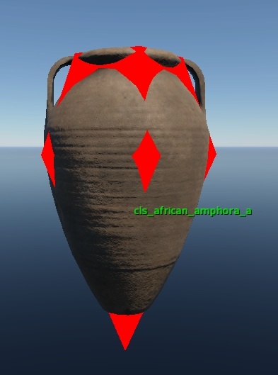
Example: The convex collisions provide detailed yet relatively efficient
processing.
Use convex (or box) collisions whenever appropriate, especially for
frequently repeated objects, to optimize collision handling. However, do not
sacrifice collision quality just to use convex.
capsule
Capsule-shaped collision. More efficient than mesh but less efficient than
box.
Like the box type, this parameter creates a capsule around the bounding box of
the collision geometry and treats it as such only when the property is
specified.
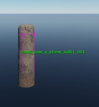
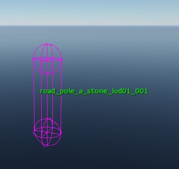
Example: The capsule collision type is used for cylindrical objects.
Since few static objects have simple cylindrical shapes that can be represented
by one or two capsules, this type is rarely applied to static objects. It is
more commonly used in destrs, where cylindrical parts can be isolated and
assigned capsule collisions.
Parameter: phmat:t=""
This parameter defines the physical material assigned to an object, ensuring appropriate sound effects for impacts, decals, and footsteps are applied to its surface.
It is specifically applied to collision geometry. For objects using multiple materials, the collision geometry must be segmented accordingly, with each segment assigned the correct physical material.
Important
For objects featuring both trace and physical collisions, physical materials (“physmats”) must be defined for both collision types.
Physical material names are predefined and must adhere to established naming conventions. To view the physical material assigned to a collision in Asset Viewer, select the collision geometry in the viewport. The object’s properties panel will display the assigned physical material.
See also
For more information, see Physmats.
This approach also serves as a validation method: if “default” appears instead of the expected physmat, it indicates that an invalid or no physical material has been assigned.
The following physical materials are most commonly used for props:
Material Type |
War Thunder |
daNetGame-based |
|---|---|---|
Vegetation |
|
|
Hard stone |
|
|
Earth |
|
|
Metal |
|
|
Cloth |
|
|
Man-made |
|
|
Hard transparent |
|
|
If the required physmat is not available, attempt to locate the closest matching material. If no suitable alternative exists, submit a request for a new material to be created. Avoid assigning a non-existent physmat arbitrarily, as this will cause the system to default to the generic “default” material, resulting in unintended behavior.
Asset managers can review the current list of physical materials in the
physmat.blk file. For War Thunder, this file is located at
<project_name>/develop/gameBase/config.
daNetGame-based Project Parameters
These parameters are specific to daNetGame-based projects and must not be used in War Thunder.
isPhysCollidable:b=yes/noisTraceable:b=yes/no
Important
It is essential to understand that these parameters operate independently. Each controls a distinct aspect of collision behavior, with no overlap between them.
For example, physical collision may be defined as convex, while trace
collision can use a box type. These represent separate systems that function
without interfering with one another.
Parameters: isPhysCollidable/isTraceable
These parameters are presented together because, although they operate independently, they are frequently used in conjunction. Neither parameter disables the other; instead, each explicitly indicates the intended purpose of a specific collision.
By default, collisions are treated as applicable for both physical interaction and tracing. Therefore, defining a collision without specifying these parameters leaves ambiguity about its role.
Important
If an object contains multiple collision meshes and one mesh is explicitly designated as either a “trace” or “physical” collision, you must assign corresponding parameters to all other meshes. Failure to do so will cause those meshes to inherit the properties of the explicitly defined mesh, potentially resulting in unintended trace-only or physical-only collision behavior.
isPhysCollidable:b=yes: This parameter designates collisions that interact exclusively with the character’s capsule. Since most player-environment interactions occur through the capsule and exclude shooting, these collisions do not register interactions with weapons. Players can shoot, slash, or strike through them without obstruction.Collisions marked with this parameter are simplified to approximate the general shape of objects or object parts with which the player physically interacts, such as surfaces to walk on or obstacles to collide against. This simplification is critical because capsule collision processing is computationally expensive; the simpler the collision geometry, the lower the performance cost.
isTraceable:b=yes: This parameter indicates that the collision interacts exclusively with the player’s weapons, including shooting and melee attacks. It does not interact with the character’s capsule, allowing the player to move through it freely.Collisions assigned this parameter are made more precise than physical collisions, but only to the degree necessary for accurate bullet tracing. The objective is to create a collision that sufficiently covers the shootable geometry without unnecessary detail. For example, it is not required to include every door handle or small metal rivet on a wooden door just to produce accurate hit decals.
Important
Trace collision is not without computational cost. Avoid applying trace collision to non-essential geometry that does not affect bullet tracing, even if it improves visual accuracy for decals. Apply trace collisions only to objects that impact gameplay or are large enough that inaccurate decals would be noticeable.
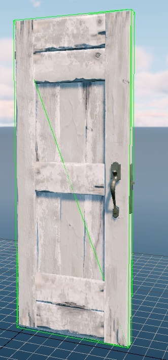
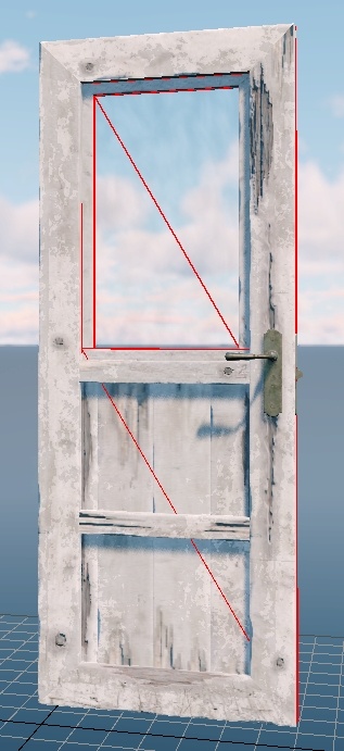
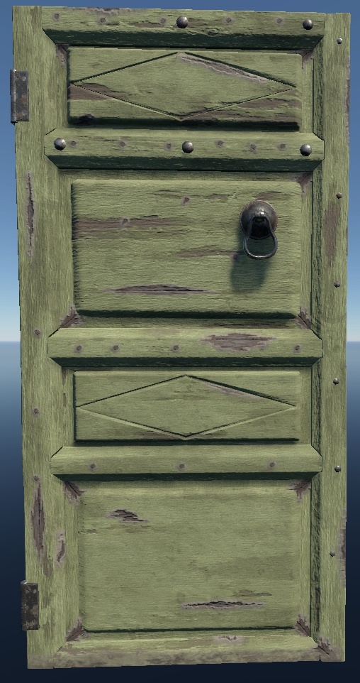
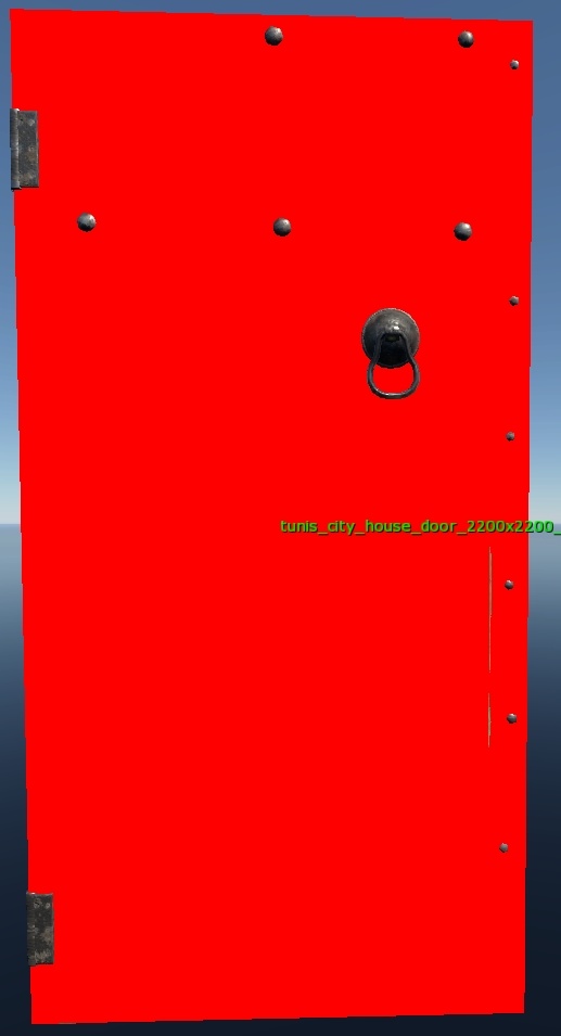
For a door, trace collision should only cover the wooden panel, as the rest of the structure doesn’t affect gameplay and is too small to justify the added complexity.
In this case, glass was assigned its own collision and separate material because it is easier to shoot through than wood, affecting bullet penetration, and because its large surface area would look unrealistic if wooden decals appeared on it.
Important
A specific engine behavior to keep in mind: characters interact with physical collisions using their capsule, but foot placement relies on trace collisions.
For example, consider a large object with a recessed center, such as a flower bed that the player can climb onto but cannot shoot through in the recessed area. In this case, the trace collision must accurately include the recess to ensure correct foot placement. The physical collision, however, should remain simplified and exclude the recess to reduce processing cost.
If the trace collision does not reflect the actual surface geometry, the character’s feet may appear to float or walk on air, as foot placement is guided solely by the trace geometry.
Collision Separation Principles
The core principle is simple: if an object needs to support both physical and trace interactions, create two separate collision meshes, each optimized for its specific purpose.
Physical collisions should be as simple as possible. Use convex shapes, capsules, or boxes whenever feasible to minimize performance cost.
Trace collisions should be only as detailed as necessary to accurately capture bullet paths and significant material surfaces. Avoid unnecessary complexity that does not affect gameplay.
How to Assign Parameters
Collision parameters must always be specified in pairs: isPhysCollidable
and isTraceable. These should never be assigned individually, as doing so
may lead to inconsistent or unintended behavior.
isPhysCollidable:b=yes|isTraceable:b=yes: These are the default values. You may specify them explicitly, but it is not required. Including them is not considered an error, though it adds no functional value.isPhysCollidable:b=no|isTraceable:b=no: This combination serves no practical purpose. If the collision is not needed at all, simply set the primarycollidable:bparameter tono.isPhysCollidable:b=yes|isTraceable:b=no: Enables physical collision only. The object will block player movement (e.g., walking or driving) but will not register weapon traces,bullets and projectiles will pass through.Important
Append the suffix
_physto the collision node in the scene to indicate its role.isPhysCollidable:b=no|isTraceable:b=yes: Enables trace collision only. The object will block bullets and projectiles but will not obstruct player movement—characters and vehicles can pass through it.Important
Append the suffix
_traceto the collision node in the scene to indicate its role.
Guidelines for Using Each Collision Type
These guidelines focus on identifying when a particular type of collision is not required. By default, both physical and trace collisions are enabled unless explicitly overridden.
Physical Collision
Avoid specifying physical collision in the following cases:
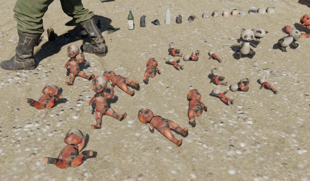
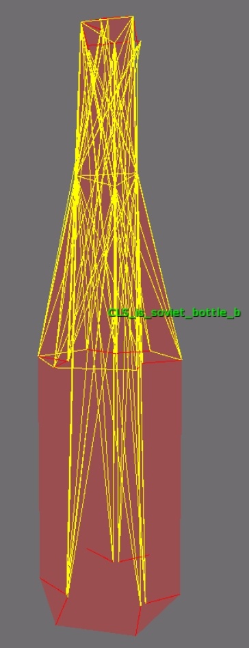
Small objects (typically less than knee height), such as scattered bricks, books, or bottles. Assigning physical collision to these would cause the player to constantly bump into them, resulting in camera jitter and disrupted aiming.
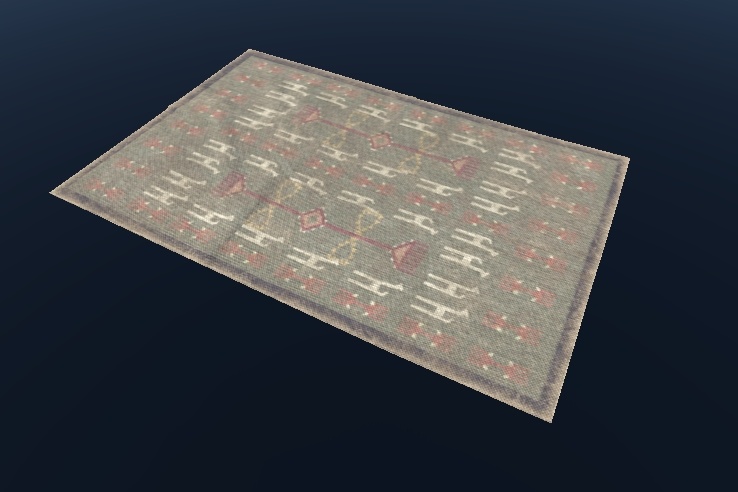
Flat surfaces that do not require a distinct physical material, such as carpets or decals.
Out-of-reach elements that the player cannot physically interact with, such as objects placed high above the playable area or inaccessible architectural details.
Example 1:
Amphora handles: These are small decorative elements that do not affect gameplay or player movement. Collisions with them would have no noticeable impact.
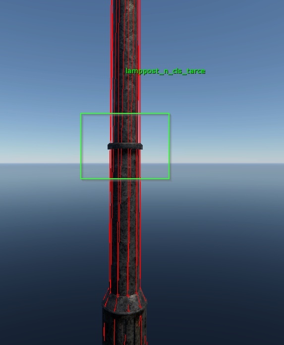
Upper sections of a pillar: If the player cannot reach or interact with these areas physically, assigning collision is unnecessary.
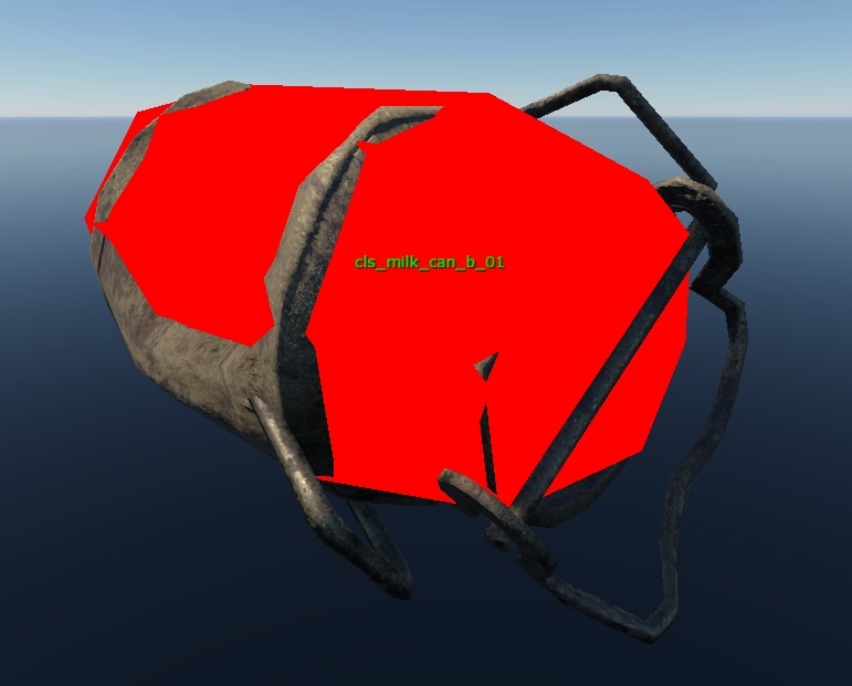
Small details on a milk can, such as handles: Like the amphora, these elements do not influence player movement or interaction and can be safely excluded from physical collision.
Example 2: Compact objects below knee height that the player should not physically collide with such as small debris or clutter should generally not have physical collision assigned. Allowing collisions on these items can cause the player to awkwardly jump or stumble over them, disrupting smooth gameplay and camera behavior.
Example 3: Flat objects such as rugs do not require physical collision since omitting a physical material will not impact the sound of footsteps or player interaction.
Trace Collision
Avoid specifying trace collision in the following cases:
Objects or parts never in the line of fire, where bullets will not realistically hit them.
Non-essential objects that players will not engage with in detail; these should have simplified collision by removing unnecessary elements.
Parts covered by other collision meshes, such as roof beams hidden beneath the main roof geometry.
Objects where shooting serves no gameplay purpose, for example:
Books or bricks on the floor that do not break, where the ground impact particle effect is sufficient.
Posters on walls that do not break, where the wall impact particle effect is appropriate.
Carpets on floors that do not break, where the floor impact particle effect will suffice.
Example 1: Handles on an amphora are too small and insignificant to be considered in the line of fire.
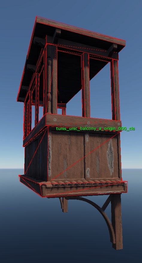
Example 2: Beams under a ceiling are unlikely to be shot at, similar to balcony supports attached to walls.
Example 3: Thin shootable elements should not have excessive collision detail as it may interfere with gameplay by obstructing shots.
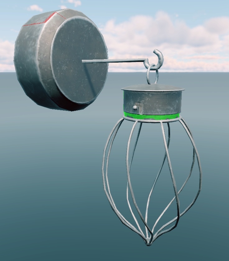
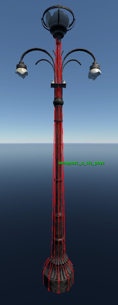
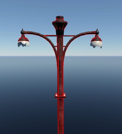
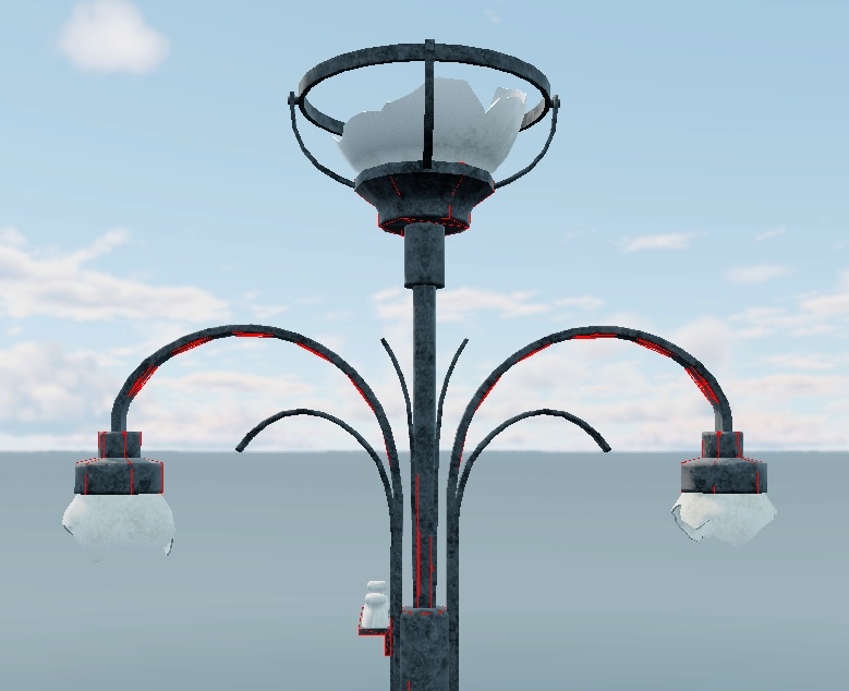
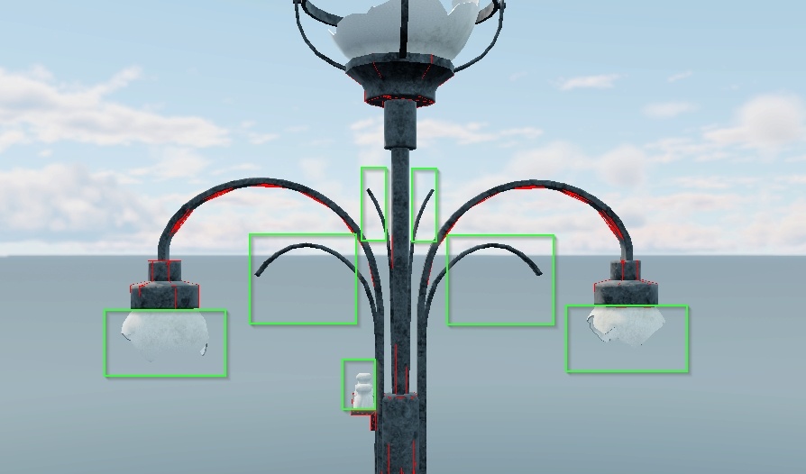
Example 4: Objects like light fixtures should be shootable but there is no need to allocate extra polygons for their collision.
Example 5: Trace collision is unnecessary for objects that do not need to be shot through.
Collision Design Principles
Effective collision handling relies on several fundamental principles:
Collision geometry should be closed to ensure reliable physics interactions.
Collisions must not extend beyond the visible geometry to prevent unexpected clipping or blocking.
All parts of the object relevant to player interaction must be included.
Collision meshes should be highly optimized to minimize performance impact.
These principles can seem contradictory, as some call for detailed accuracy while others emphasize efficiency. The key challenge is to find the right balance between precision and optimization.
Important
It is essential to differentiate collisions based on an object’s size and gameplay role:
Gameplay-relevant objects, such as those in the line of fire, require higher collision accuracy, especially for trace collisions, compared to non-gameplay objects like props that do not affect bullets or visibility.
Large objects warrant more detailed collision meshes for both trace and physical collisions than smaller objects.
Closed Collision Geometry
Collision geometry that contains holes, open edges, or consists of simple planes can cause clipping issues where objects unintentionally pass through each other. Therefore, as a fundamental rule, collision geometry must always be closed.
When separating physics and trace collisions, trace collisions which are generally more detailed may omit unseen faces such as those intersecting other collision geometry. However, physics collisions must always maintain closed geometry to ensure reliable physical interactions.
Fitting Collision to Visible Geometry
The principle is straightforward: in a shooter game, when a player shoots at an enemy, and the projectile hits an invisible barrier instead of the visible object, it diminishes the gameplay experience. This makes precise collision handling essential.
Important
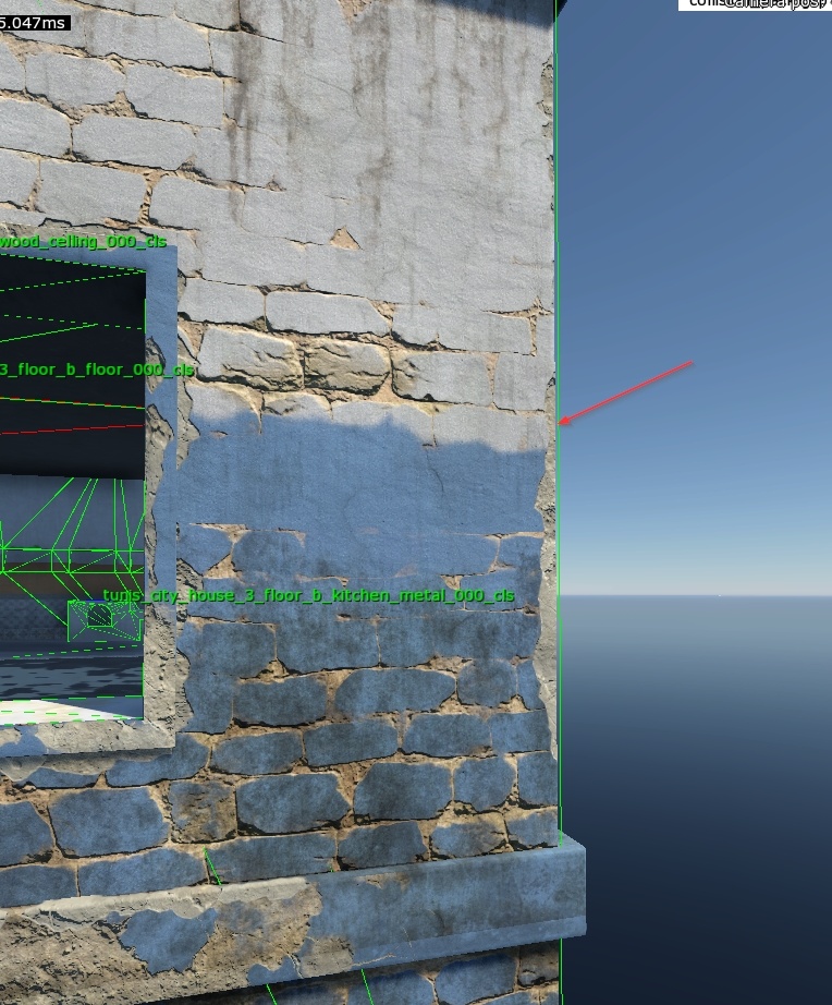
Additionally, note that occluding geometry, such as building walls, relies on trace collision. Extending this collision geometry even slightly beyond the building’s visible boundaries can cause occlusion bugs, including incorrect object visibility when peeking around corners or aiming down sights.
Example 1 (Good): A Level of Detail (LOD) model has been optimized by removing unnecessary loops. Minor protrusions in the collision geometry that do not affect gameplay or bullet interaction are acceptable.
Example 2 (Good): A small amphora, while not gameplay-critical, may have minor collision geometry extending beyond the visible object. This does not impact the game experience since the item is destructible.
Example 3 (Good): The main geometry is properly collidable. Unnecessary objects that do not impact gameplay are excluded from collision. For example:
Ceiling beams do not affect the line of fire.
Balcony fixtures are highly unlikely to be in the line of fire.
Example 4 (Moderate): Only important geometry is included in the collision mesh. Unnecessary elements that do not influence gameplay, such as beams or ceiling mounts, are excluded from the collision setup.
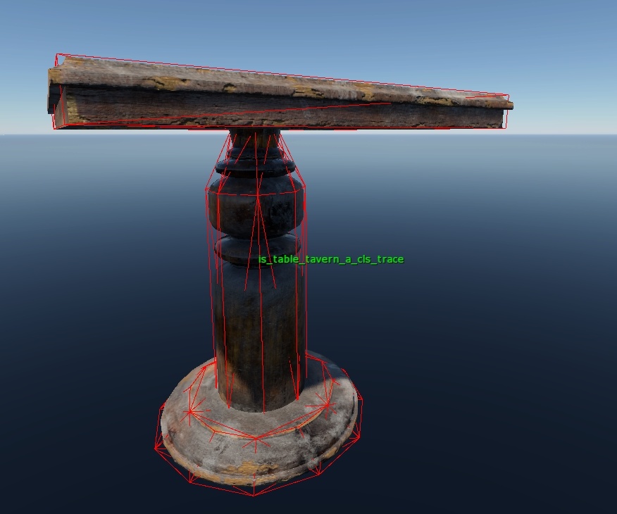
Example 5 (Moderate): The change in the width of the table leg should be represented in low-poly form. While shots fired at this area are unlikely, indoor crouch firefights remain a possibility.
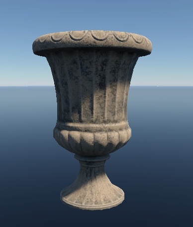
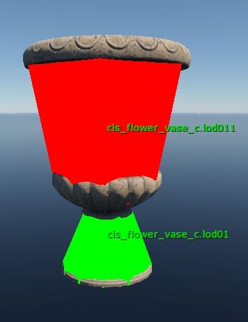
Example 6 (Poor): Large vases with collision geometry covering empty spaces can cause significant issues by creating unintended non-destructible barriers during gameplay.
Example 7 (Poor): A large vase with extensive empty spaces included in the collision mesh is a definite bug.
Example 8 (Poor): A house wall acts as an occluding object. Even minimal collision protrusions can cause objects to disappear from rendering. This was a previously fixed bug and illustrates how a narrow collision strip creates a real, non-penetrable space despite appearing thin.
Describing Important Parts
It is essential to distinguish which parts of an object require collision and which do not.
Example 1: Small handles on an object do not need collision. They should neither stop bullets nor cause the object to break unnaturally.
Example 2: Balcony attachments do not require detailed collision as they are unlikely to affect gameplay.
Example 3: There is no need to add collision for small, non-destructible elements such as broken lamps or decorative insulators.
Example 4: Very small elements do not require collision.
Example 5: Apart from the door itself, there is nothing else that requires collision. Either the object faces the player, making collision details irrelevant, or it is open with protruding parts against the wall, meaning they do not impact gameplay.
Collision Optimization
In addition to the principles outlined above, collisions must be optimized by using the minimal amount of geometry necessary while still adhering to all guidelines.
There is no universal rule for this process; the goal is to reduce polygon count as much as possible without compromising gameplay or bullet interactions.
If you can remove unnecessary polygons without affecting how bullets or players interact with an object, you should do so.
Simple Collisions: box, convex, capsule
As mentioned earlier, the engine uses three basic types of collision shapes:
box: A rectangular collision volume processed as a box rather than a rectangular mesh. This is the simplest and most efficient collision type.convex: Convex geometry handled as a convex shape instead of a convex mesh.capsule: A capsule-shaped collision object.
The behavior of these collision shapes depends on both the object properties
(see the collision:t="mesh" parameter) and the geometry itself.
Important
It is important to understand that simple collision shapes improve performance only when applied to entire objects. Using multiple boxes or convex shapes to approximate a complex object like a table does not optimize performance. In such cases, it is better to use a standard mesh. However, if the collision can be described with one or two simple shapes, such as a box, convex, or capsule, you should do so.
Box Collision
Box collision is calculated based on the bounding box of an object, with the
collision type assigned as box.
If you rotate a box collision in 3ds Max, it will not rotate in the Asset Viewer. Instead, the bounding box will be recalculated to align with the world axes. You can scale, move, and manipulate the box’s faces along the axes, but rotating or moving polygons outside these constraints is not supported.
Convex Collision
Convex collision is generally simpler to handle but may sometimes behave unexpectedly in the Asset Viewer, even if it appears correct in 3ds Max. This often indicates the presence of concave triangles, which can be difficult to detect and usually require reworking the model’s triangulation.
Using tools like the MassFX modifier in 3ds Max can simplify this process.
3ds Max: MassFX modifier
MassFX Modifier Parameters:
Shape: Set to
convexsince we are working with convex geometry.Generate From:
Vertices: Use this option if you want the collision to fit closely to the mesh.
Surface: Use this option to approximate the mesh with collision.
Vertices: Adjusts the vertex count, which affects the polygon count of the collision mesh.
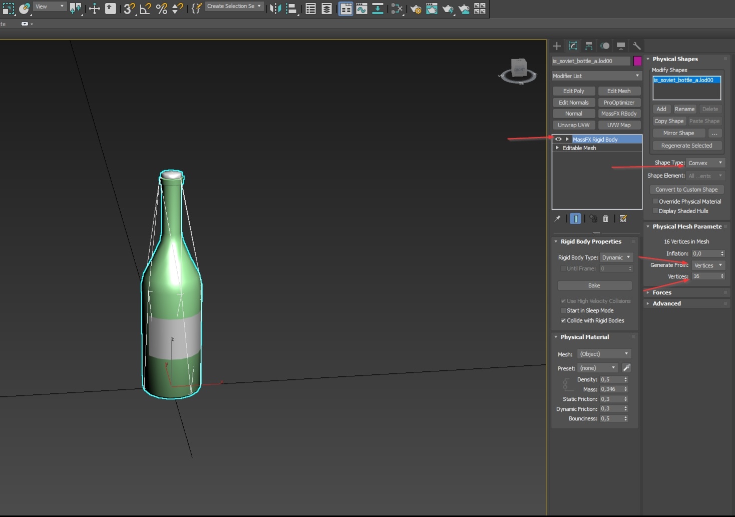
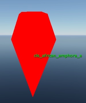
Often, you will need to remove parts of the mesh before generating the convex collision, especially for complex objects. For example, when creating a collision for a vase model, removing the handles can simplify the convex hull around the main body of the vase.
Optimizing Convex Collision
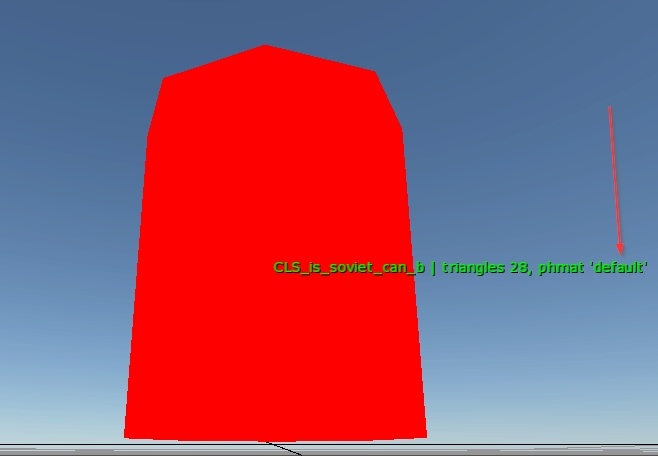
A common misconception is that because convex collisions are computationally cheaper than mesh collisions, their polygon count is irrelevant. This is not true. You should always strive to minimize the polygon count of convex collisions.
For example, creating a 28-triangle convex collision for a small 10-centimeter-high tin can is excessive. Instead, simplify the polygon count to the minimum necessary for accurate collision handling.
Capsule Collision
Capsule collisions do not present unique challenges but should follow the same principles of optimization and appropriate use. Avoid overcomplicating the geometry when a simple capsule shape is sufficient.
Parent-Child Collisions
The engine supports chain destruction with up to two levels of links. You can designate an object as the parent, and by default, other objects without this designation become its children.
When a parent object is destroyed, its child objects are destroyed as well. For example, when a kitchen table breaks, plates placed on it will shatter accordingly. This behavior is configured through destruction settings and does not affect the model itself.
However, an important limitation applies: destruction of child objects only occurs if the child’s collision geometry is fully contained within the bounding box of the parent object’s collision.
For example, if a plate’s collision is flat and positioned just above the table’s surface, it will not be destroyed when the table breaks.
Key Rule
The collision geometry of any object resting on a destructible object must extend inside the bounding box of the destructible object for the destruction chain to function correctly.
For example, consider the collision geometry of amphoras that rest on destructible surfaces. Notice how their collision geometry extends downward into the bounding box of the supporting surface to ensure proper destruction behavior.
Important
The chain destruction system operates strictly in one direction: parent → child.
Destroying a child object does not affect the parent; the parent remains intact.
Destroying a parent object only affects children whose collision geometry intersects the parent’s bounding box. Children without such intersection will remain undestroyed.
Therefore, always designate assets placed on other objects as children, and the supporting objects as parents. Currently, multi-link destruction chains beyond two levels are not supported.
Example Scenarios of Parent-Child Combinations
Parent
Child
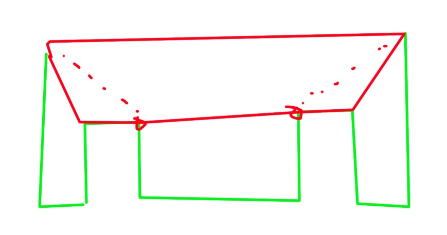
Below are four examples of parent–child combinations:
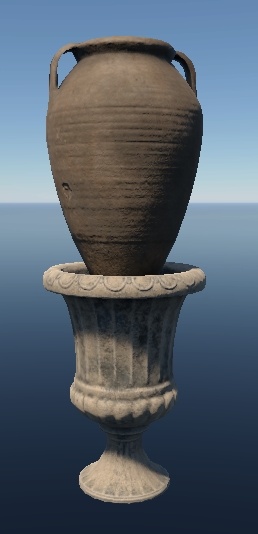
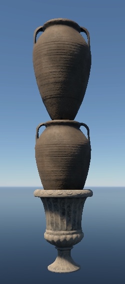
Example 1: Correct. The child’s collision (the extended base) intersects with the parent’s bounding box. Destroying the parent will also destroy the amphora.
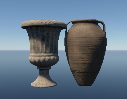
Example 2: Also correct. The side collision of the amphora intersects with the urn’s bounding box. Destroying the urn will break the amphora.
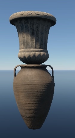
Example 3: Incorrect. The parent object is floating in the air. If the parent is destroyed, the amphora will also shatter, but if the amphora is destroyed first, the parent will remain floating.
Example 4: Incorrect. Only one amphora (the middle one) intersects the parent’s bounding box. Destroying the parent will only destroy the middle amphora, while the upper one will remain suspended in mid-air.
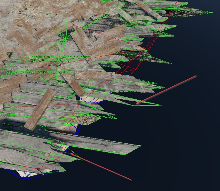
Collision Naming Conventions in 3ds Max
Consistent naming is essential for clarity and proper asset processing. Follow these conventions when naming collision geometry:
Use the
_clssuffix for all collision objects.Base the name on the original 3ds Max object the collision is intended for. For example, if the visual object is named
table_leg_lod00, the collision object should be namedtable_leg_cls.For physical collisions, add the
_physsuffix, for example:table_leg_cls_phys.For trace collisions, add the
_tracesuffix, for example:table_leg_cls_trace.
Typical Collision Problems and Pitfalls
The following technical errors in collision geometry can lead to significant problems:
Unclosed geometry in physical collisions.
Degenerate triangles.
Inverted normals.
Missing triangulation in complex physical collision geometry.
Unclosed Geometry in Physical Collisions
As previously mentioned, physical collision geometry must be closed. There are no exceptions to this rule.
Degenerate Triangles
Collisions containing degenerate triangles can cause client crashes when interacting with characters or players.
Causes
Degenerate triangles arise from:
Actual degenerate triangles (collapsed or zero-area triangles).
Unwelded vertices with duplicate edges.
Isolated vertices (vertices not connected to any geometry).
Detection Methods
Degenerate triangles can be identified through:
3ds Max export logs, which flag classic degenerate triangles during the export process.
Console output in the Asset Viewer, which will display errors such as:
stalingrad_city_balcony_1500x2000_a_collision: degenerate tri 10,13,11:
(0.910, -1.404, 0.731), (0.983, -1.477, 0.731), (0.990, -1.484, 0.731)
(edge len: 0.103137, 0.00999993, 0.113137)
Fixing Methods
Degenerate triangles can be resolved through various methods:
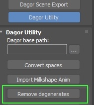
Remove degenerates using the built-in Dagor Utility.
Weld vertices with a very small delta (e.g., less than 2 mm) to ensure the shape of the geometry is not altered.
Remove isolated vertices through the remove isolated vertices command.
Important
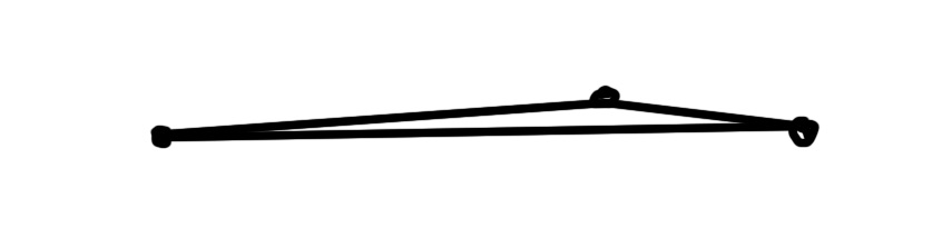
Some issues may require manual intervention. For example, long, thin triangles may not be fixed by automated tools. In such cases, inspect the coordinates of problematic vertices and manually correct the geometry.
Inverted Normals
Inverted normals in collision geometry can cause characters to stick or appear to be glued to the surface.
Causes
Inverted normals typically result from:
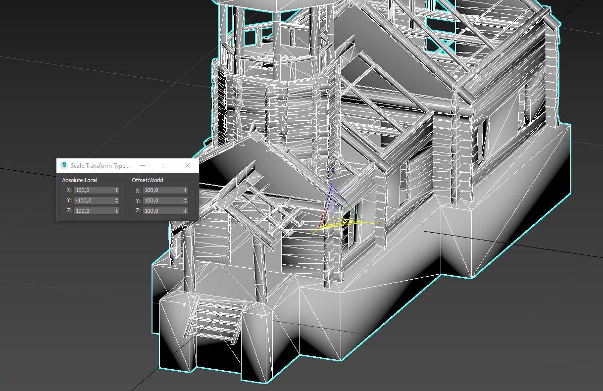
Negative scale matrices (even though normals might appear correct in 3ds Max).
Flipped polygons.
Detection Methods
Flipped Polygons
Flipped polygons can only be detected visually in 3ds Max; they are not flagged automatically.
Inverted Scale Matrices
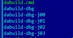
Inverted scale matrices can be found in the daBuild logs. Use the following steps:
Run daBuild (you can run it just for collisions for faster results):
../../tools/dagor3_cdk/bin64/dabuild-dev.exe ../application.blk -q -dry_run -only_res -jobs:3 -rebuild:collision collision_pack.grp
Locate the daBuild logs
Search for “bad mesh node” entries. Errors will look like this:
34.67 [W] geschutz_wagen_rendinst_collision: bad mesh node "Object020" tm={(1.400,0.000,-0.000) (-0.000,-0.000,-1.400) (-0.000,1.400,-0.000) (0.000,0.000,0.000)}
Missing Triangulation in Complex Physical Collisions
Causes
This issue typically occurs when:
Complex collision geometry has not been properly triangulated manually.
The geometry contains unwelded edges or problematic vertices that cannot be resolved automatically.
Cut-outs or holes in the collision mesh are left untriangulated, further compounding the problem.
These conditions can result in invisible barriers, preventing the player character from moving through spaces that appear visually unobstructed. The issue may only occur from certain directions or cause the character to get temporarily stuck before passing through.
Detection Methods
Unfortunately, there is no automated way to detect this issue either in-game or through available tools. The only reliable solution is manual inspection and correction.
Ensure clean, well-formed physical collision geometry For example, in the case of a problematic stair collision, rebuilding the geometry and applying proper triangulation resolved the movement issue.
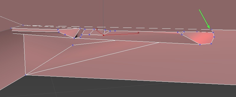
Manually triangulate geometry near passageways While the root cause is often flawed geometry, manual triangulation in key areas, especially around tight walkable spaces—can frequently mitigate the problem.
Collision Handling in .folder.blk
Collision resources, like all other assets, are processed by the engine through
the .folder.blk configuration file. A typical collision processing block looks
like this:
virtual_res_blk{
  find:t="^(.*)\.lod02\.dag$"
  className:t="collision"
  name:t="$1_collision"
}
In this example, lod02 refers to the Level of Detail file used for collision.
You can substitute this with any LOD level as needed, depending on where the
collision geometry is placed.
Important
As of October 2023, the approach to collision processing has changed. We no
longer define individual virtual_res{} blocks within .folder.blk for
War Thunder and daNetGame-based projects.
Instead, collision processing is handled through pre-configured files located
at: <project_name>/develop/assets/.
These files include:
_ri_collision_lod0_continue.blk_ri_collision_lod0_stop.blk_ri_collision_lod1.blk_ri_collision_lod2.blk_ri_collision_lod3.blk_unit_collision_dm.blk_unit_collision_dynmodel_lod0_continue.blk_unit_collision_props.blk
Each file contains virtual_res{} blocks similar to those used previously,
but now includes additional references to shared configuration files. These
referenced files contain specific parameters required for various collision
types (for example, different settings for render instance collisions versus
unit collisions).
For example:
virtual_res_blk{
  find:t="^(.*)\.lod02\.dag$"
  className:t="collision"
  name:t="$1_collision"
  contents{
    include "#/develop/assets/_ri_collision_props.blk"
  }
}
The new system uses predefined include files to configure collision processing consistently across all assets. These files contain essential parameters such as:
collapseAndOptimize:b=yes: Enables additional geometry optimization and compression during packaging.buildFRT:b=yes: Enables building for the FastRayTracer.
The exact parameters are less important than the fact that they are
automatically applied to all render instance collisions via these include
files. To maintain this behavior do not manually define collision
processing using virtual_res{} blocks anymore.
To include collision processing for a specific LOD, simply add the relevant
include file to your .folder.blk. For example:
include "#/develop/assets/_ri_collision_lod1.blk"
Replace the file name as needed depending on which LOD level you are working
with. This line can be placed anywhere in the .folder.blk file and does
not require a virtual_res{} block.
This approach ensures consistency, reduces redundancy, and aligns with the current asset pipeline.
Usage Examples
Exclusion Example:
include "#/develop/assets/_ri_collision_lod2.blk"
"@override-last"{ exclude:t="^(.*sign.*)\.lod02\.dag$"; }
Name-Based Search Example:
include "#/develop/assets/_ri_collision_lod1.blk"
"@override-last"{ "@override:find":t="^(.*pos_a.*|.*pos_b.*|.*pos_c.*|.*sign.*)\.lod01\.dag$"; }
In both cases, we use @override-last to modify the behavior of the previously
included blocks, allowing for custom exclusions or searches based on specific
patterns.